
Container Water 05: The new Normal
I didn’t want to age any of these posts my making 2020 references, but for an article about creating new normals… I couldn’t help it.
I just wandered through the process of putting together the first iteration of the fluid shader, but I was not happy with how the recalculated surface normals had turned out using ShaderGraph’s “Normal from heightmap” node. Vertex deformation in shaders wasn’t exactly new to me, however I’d not needed to re-compute the surface normals before – previous modifications hadn’t been drastic enough, so time to get my hands dirty-er.
The problem
When one alters meshes with shaders in Unity, it’s important to remember that doing so does not alter the mesh’s surface normals to make up for this. This is a fairly obvious truth in hindsight, but until you’ve seen the issue and correct it, it’s a fairly abstract one.
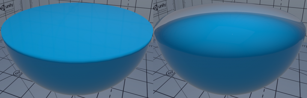
As you can see from the above, not recalculating the surface normals looks very broken, as despite being a flat surface perpendicular to the y-axis, the mesh’s still being lit as if it were a sphere.
Now the former example is somewhat a cheat. There’s no magic there, I’m simply setting the new tangent space normal to face along the point-on-plane’s impact normal, which happens to be perfectly up. This works fine as the surface is perfectly flat and uniform, but the following gif shows why this soon is wrong.
Granted, this isn’t as noticeable as spherical shading on a flat surface, but equally here, I’ve lost all sense of normal shading, causing the surface to look perfectly flat aside from the edges.
The Solution
The solution here is not quite as complicated as it might seem, at least, the theory isn’t – assuming we don’t want our surface to have any new / additional hard edges.

To find the new vertex normal, you sample 4 neighbouring points on the surface, in both the x and y axis, and in positive and negative directions. You then cross product the x+ and y+ (which effectively become the new tangent and bitangent) to get your new normal. Do the same with the x- and y- and you have two new normals.
Now average our your two new normals and you have yourself your recalculated normal for that point on your surface.
Getting the Surface Data
The main requirement of this approach is that you have the ability to access the surrounding surface to perform the above calculations.
I initially used a 1 dimensional buffer of spring heights and transposed this buffer into a 2D grid, a representation of the fluid’s surface so I can get neighbouring points easily.
I’m now reading from the spring heightmap texture as because it’s bilinear filtered, I get some smoothing for “free” rather then the quite harshly stepped look I’d get otherwise.

Right: Unfiltered spring buffer sample
Both images above are recalculated normal maps from spring height data encoded in object space.
Another way so sample the surrounding surface data, is to create a custom buffer (ComputeBuffer and its HLSL counterpart, StructuredBuffer). In to this, you pack list of each vertex Id, with each element in the buffer containing an array of the current vert’s neighbouring vert positions. Inside the vertex program in the shader, you can then read this buffer using the VertexID (using the SV_VertexID semantic) as the buffer read index.
This allows you to get the neighbouring vertex positions, in the vertex shader, as long as this the same as any vertex position after modification. So keeping this buffer updated using C# or Compute Shaders is necessary, and a pretty big caveat to this approach.
(ShaderGraph doesn’t provide any interface to do this so far that I’m aware of)
Because I’ve recomputing normals based on a texture, another variable I have to play with is the distance on the height map texture or how far from the current point I sample.

The closer to the current surface point is surface, the “sharper” the calculated normals will be, as seen above. Further away, results in a smother, and slightly more stable result. When sampling mesh data directly, you don’t have this level of control, unless you go to greater lengths to arrange the geometry data you send to your shader.
Compute or Fragment
The “obvious” place to do the normal recalculation is the fragment function of the shader. So naturally the implementation I tried was via compute shader… I didn’t have a good reason for doing it this way at the time, other then being in the compute neighbourhood. The following is the code from the kernel.
// Sample value at outTex for current pixel
float2 coord = id.xy / (float)res;
float3 p = float3(coord.x, GetSpringHeight(coord), coord.y);

// Get neighbouring positions
// TODO: Catch for out of range coords - doesn't seem to be a
// problem because of texture sample wrapping
float2 n1c = float2(coord.x + normalOffset, coord.y);
float2 n2c = float2(coord.x, coord.y + normalOffset);
float2 n3c = float2(coord.x - normalOffset, coord.y);
float2 n4c = float2(coord.x, coord.y - normalOffset);

float3 n1 = float3(n1c.x, GetSpringHeight(n1c), n1c.y);
float3 n2 = float3(n2c.x, GetSpringHeight(n2c), n2c.y);
float3 n3 = float3(n3c.x, GetSpringHeight(n3c), n3c.y);
float3 n4 = float3(n4c.x, GetSpringHeight(n4c), n4c.y);

// get vector from pixel to n
float3 pn1 = n1 - p;
float3 pn2 = n2 - p;
float3 pn3 = n3 - p;
float3 pn4 = n4 - p;

// Cross prod of vectors, order of terms is important
float3 normal1 = normalize(cross(pn2, pn1));
float3 normal2 = normalize(cross(pn4, pn3));
float3 summedNormals = normal1 + normal2;

// Average vectors to find new normal, catch zero-length vectors
// as normalizing them creates unstable results
normalTex[id.xy] = length(summedNormals) > 0
                          ? float4(normalize(summedNormals),1)
                          : float4(0,1,0,1);

// Pack normals into 0-1 range
normalTex[id.xy] = normalTex[id.xy] * 0.5 + 0.5;
In recalculating the surface normals via a compute shader, I end up with a normal map, which is both good and bad. Good because it’s a fixed cost, and I get a texture I can debug it easily.
It’s bad however, because every frame (or every time I dispatch the compute shader), I’m recomputing normals per pixel, for every pixel of the normal map, not every visible pixel of the final surface shader. This means I will be running more math operations and texture samples for computing pixels which aren’t visible to camera – and always at the highest resolution.
I intend to benchmark the difference between the two methods of normal calculation soon, it would be good to have an empirical understanding of the differences rather then simply theoretical, however for now it’s working, and doesn’t seem to be causing an issue.
Debugging the Problem Along the Way
So far it might seem like I’ve got everything in order… unless you know something I don’t, in which case please share.
But I did run into a problem along the way with this one, some minor copy and past mistakes, but the main issue was getting the order of the vectors correct in the cross product function. Turns out getting them the wrong way around flips the returned normal.
This however isn’t the point of this segment, more an aside on debugging code in GPU land. One of the benefits of doing stuff with shaders (at least in Unity) is the iteration time. Save the shader, ctrl-r in Unity, and after a second or 2 (or more if it’s a full HDRP/ShaderGraph shader) everything is updated, even at runtime.
This contrasts to refreshing C# code which requires a compile of the assembly the file is a part of, which can take much longer, and is not always a stable thing to do when in ‘play’ mode.
Code executed on the CPU is much easier to debug however. It’s possible to log out values to console very easily, you can step through code line-by-line, and in Unity it’s very easy to draw debug Gizmos to help you visualise data in the scene view and game viewports.
Debugging shaders is more abstract as the value outputted from the GPU is often just a colour value. This is fine sometimes when what you want to debug is simple, not so much however when debugging 3D math.
This is what I was returning, which was subtly wrong, and I needed to debug. The difficulty with debugging shader math via colours is representing “negative” vectors – it’s hard to represent a -1 to 1 floating point value in a format which only caters for 0 to 1 ranges.
Tangent-space normal maps address this issue by remapping this range, so 0 becomes -1, and 0.5 becomes 0. Whilst this makes sense, it’s still not the easiest thing to visualise, espicially with subtle issues.
So to solve my issue, I re-implemented my normal map recalculation on the CPU so I could step-by-step debug what was happening, and visualise with Gizmos. This isn’t an original idea, but if often surprises me how long it takes others (and me) to step back from the problem, and write some good debug visualisations.

This rather satisfying gif shows my debug Gizmos that I wrong, it looks rather like a flexible bed of nails, but the white line segments represent the newly calculated (CPU) normal. Working rather nicely I think.
A few things to bear in mind with this, it’s important to ensure the the math on the CPU and GPU is identical – obviously. What’s less obvious sometimes is slight differences in equivalent math functions in different languages.
Take the step() function, a HLSL staple. Unity’s newer HLSL-like mathematics library for a time had a different argument order to the more familiar implementation, a subtle slip up if you’re not aware of it.
The other thing, getting data back from the GPU can be slow, very slow. How slow depends on the data your returning, the render pipeline, and the graphics hardware. This post explains better then I can the issue, but the important takeaway here is, don’t be asking for data back from the GPU lightly, and if it’s debug, make doubly sure it’s not doing it all the time.
In my example able, when I turn the Gizmos on, only then do I start asking for the spring height back from the GPU via the GetData() call.
Object to Tangent Space
My last stop on this trip, it’s to address which co-ordinate space I’ve been computing normals in, and that’s object-space.
This wasn’t so much a conscious decision as the path of least resistance, and easier to get my head around. ShaderGraph (and surface shaders) typically expect tangent-space normal maps (here’s a summary of why), so there’s the need to convert the normal maps from object-space to finish things off.
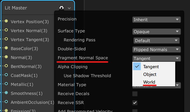
ShaderGraph rather helpfully allows you to change the component space the shader’s master node expects, but if you’re in HLSL land, you need a little more code. Thankfully, ShaderGraph’s documentation also happens to tell you what it’s doing under the hood (certain nodes at least).
This about wraps it up for this problem, next post I’m going to address the growing thorn in my side, using ShaderGraph.