
Container Water 04: Creating the “First” Shader
Now that we have the two main visual foundations of this effect ready (the general shape, and the surface sim), it’s time to put them together in a shader. As I am Fish is the studio’s first project using Unity’s HD Render Pipeline, this is going to be an interesting experience, and my first real foray into Shader Graph.
Spoilers, I’m not a fan so far.
Up until this point, my experiments had all been using the Built-in Render Pipeline, and thus all written in HLSL. Owing to the dependency on HDRP, and the lack of documentation on writing shaders in the “old fashioned way”, it’s time to go Shader Graph.
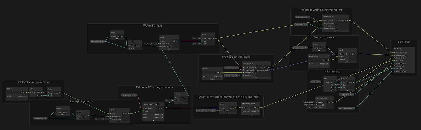
The above is a screenshot of the shader graph for the fishbowl. It’s not as complex and as overbearing as graph-based shaders can get, and there’s a couple of reasons for that.
First reason, as mentioned in 01, is the use of custom nodes. Even relatively straight-forward geometric functions can still be fairly cumbersome in “node form”. Having short code snippets, or totally separate HLSL includes are handy to keep graphs manageable and keep logic in a more digestible format (for me at least).
ShaderGraph does support making “subgraphs” of collections of nodes, so that’s an alternative avenue for organising graphs, but I prefer having shader logic as code, as it’s easier to version control and diff.
<rant>
It’s also faster to write code then build node graphs (at least as of HDRP 7.4.3) with most of the UI interactions generally being really quite slow. It’s faster to copy and paste common math nodes then open the “create node” interface up repeatedly.
Making connections in the graph is often also a slow and painful process, as with every new connection, some or all of the graph logic is re-compiled. We even have one artist who disconnects everything from the “master” node, and only reconnects when he’s finished working. This is his method of preventing Unity from it’s repeated re-compilation…
</rant>
Second reason (getting back on course), is that it’s not a massively complicated shader. The core concepts of it are at this point still pretty simple (as already outlined), and the rather nice refraction is taken care of by Unity’s new Screen Space Refraction (SSR).
Unity provide a good high-level overview of what this post process in HDRP offers, but in summary, it trumps the old and well-used method of refraction used in the built-in RP.
The previous technique was to use ShaderLab’s “GrabPass” feature, which allowed the shader to sample the current screen contents from a specific texture. This was often quite slow as each object using this feature would request a new texture. There is a more optimal use of this, but it’s often lesser used, especially when using Amplify’s version of this same technique.
HDRP does allow you to sample from the “Color Pyramid” (the current screen contents before refraction), so in theory you can use normal maps to create faked refraction effects as before. However, with HDRP doing things in a much more optimal single pass, and with fancy different refraction models to choose from, this also helped simplify things.
At this point I’ve not talked at detail about what the shader’s doing, so a quick outline;
Get the spring height & convert the spring height into model space
The water’s surface is stored as a height map, so it needs to map it to the container. The simulation is contained in what I’ve started to term “spring-space”, which is a normalized height (0-1 range) over a 2D 16×16 grid. However when sampling the height map, I need to map our 0-1 x/y texture reads, against the x/z model-space co-ordinates.
So I begin with the x/z position in model space, and remap/normalise this position using our bowls radius as the extents. This takes our arbitrary x/z position and gives us our texture co-ordinate for spring height.
Then with the spring height, we convert that back into model space using the radius as before.
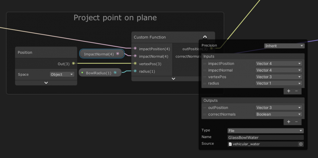
Flatten the water’s surface
Now I know what height to move the current vert to, I pass this data to my point-on-plane function. This function then returns the new position, or the original if it doesn’t need to be flattened. In addition, I get a bool from this function which I can use later in the shader to know if I need to re-calculate the surface normals.
Constrain the surface
With my new vertex position, I pass this to the sphere constrain function, which will move the vertex position back onto the sphere’s surface if it’s now outside of the bowl.
Recalculate the Normals
This is where the current iteration of the shader gets a little wonky… I’m changing the normals of the flattened verts to point straight up, to give what I thought was a solid basis for the rest of the shader.
Then for the fragment normals, I’m using ShaderGraph’s heightmap to normals node. This uses HLSL’s screen derivative functions to… well, go take a look. I’ve re-read this a few times now, and without taking some time to experiment with the function myself I still only have a vague sense of what it’s doing. DDX and DDY aren’t the most intuitive aspects of the graphics pipeline.
Anyway, this approach doesn’t exactly produce the nicest of results, so I’ll need to resolve this at a later date.
Profit???
Aside from some miscellaneous population of other surface shader features, and adding some light probe support (one node thankfully), that’s it.
Next time I’m going to be looking at creating some new surface normals